Tip: Start typing in the input box for immediate search results from our Resources Knowledge Base.
For a more comprehensive search, use the site search in the main menu above.
Manuals & Operating Instructions | Contact Support
Electrode locations in Analyzer
Electrode locations in Analyzer 2: where they are defined and how to get them right
by Dr. Nikolay Novitskiy
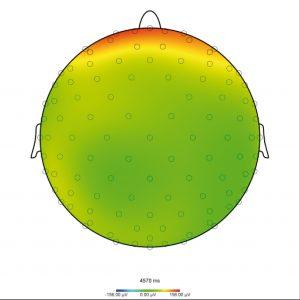
If you record data using the Brain Products hardware and BrainVision Recorder you may not have encountered the problem described in the next paragraph. Instead you will just open your workspace, select Mapping View – and voilà, the electrodes will appear on the head shape almost exactly where they were positioned during the recording of your data (see Figure 1A).
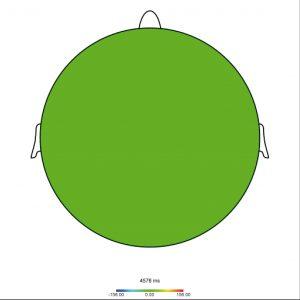
However, customers who open data recorded with different software are sometimes surprised at the result they see – namely, a map displaying a nice monochromatic circle with no sign of the electrodes (see Figure 1B). To understand why this can happen and how to prevent it we need to examine the set-up of BrainVision Analyzer’s electrode coordinate management system.

Figure 1A: Map displaying the electrode positions

Figure 1B: Map displaying a monochromatic circle
Information on default electrode positions is embedded in BrainVision Analyzer. It encompasses the spherical coordinates of all the electrodes in the 10-5 system, including not only the familiar Fz and Cz labels but also the exotic FFT7h and CPP4h. If your EEG data file contains the electrode labels of a 10-5 system (as is the case with most standard EasyCaps, BrainCaps and actiCAPs if the Recorder workspace has been properly set up), BrainVision Analyzer will recognize these labels the first time the file in the workspace is opened; it will associate the default positions with each known electrode name and save their coordinates in the history file. This is both the easiest and most highly recommended way of operating with the electrode data. Unlike other software, in this scenario BrainVision Analyzer makes it unnecessary to deal with an electrode location file. If you insert new electrodes with Topographic Interpolation or Formula Evaluator, their default locations will be also recognized. Linear Derivation is something of a special case – here you need to invoke Edit Channels to activate the insertion of default coordinates (see Figure 2).
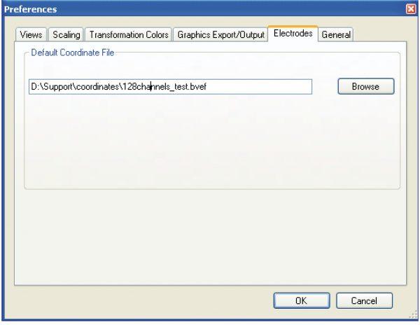
However, BrainVision Analyzer is not limited to using the predefined standard locations. You can modify the defaults or add new channel labels plus their associated positions. You can even map the locations of individual coordinates on your subject’s head and import them. This is achieved by loading a special .xml file, specifically a BrainVision Electrode File (labeled with a *.bvef file extension), as the default coordinate file in the Electrode section of Preferences (Figure 3). The structure of this file is described in the section titled “Appendix H: BrainVision Electrode Files format” in the BrainVision Analyzer manual. But lest you are disconcerted by the complexity of the .xml file structure described in that section, let me assure you that there is a less complicated and more user-friendly way to display the file. If you simply open it in Excel as an .xml table you will see orderly rows and columns of coordinates. Into this table you can copy and paste entire rows and columns and hence enter individual electrode coordinates. If you save the file in .xml format and then rename it with the .bvef extension, your BrainVision electrode file will be ready for use. By default the first line is <Electrodes defaults=“true“>. The “true” descriptor means that your coordinates will be added to the original 10-5 file (overwriting any names that coincide). But you can change the “true” descriptor to “false” so that the list only includes the locations you have defined.

Figure 2: Edit Channels
After loading the file, BrainVision Analyzer will treat those coordinates as the defaults when it reads in new datasets. Please note that pre-existing history files will not be changed unless their raw files are reloaded. For example, should you wish to change the coordinates between subjects, you will need to re-define the electrode file, restart BrainVision Analyzer and then select “Reload the Raw File” from the right-click menu of the node in order to create a new history file with new coordinates. In this way different history files contained in a single workspace can contain different sets of electrode coordinates irrespective of what electrode file is currently defined in the Preferences. When you export the data using Generic Export, the electrode coordinates of that particular node are saved in the header file. When you open the exported file or any other raw dataset that already contains information about electrode positions, any BrainVision Analyzer defaults will be overwritten. Then if you wish to match your electrodes to the defaults, just open Edit Channels and click on Default Positions. To return to the location of the parent node, click the Reset Positions button (see Figure 2).

Figure 3: Insertion of default coordinates
One possible application of the Default Coordinate File would be “importing datasets with electrodes with non-standard names”, for example E1 … E128. Although the simplicity of this system is unsurpassed, it is somewhat lacking in consistency, since the same label (e.g. E83) may relate to the occipital area of one cap and to the parietal area of a second cap. In this instance there is no way to identify the exact location from the label. Therefore information on the electrode location is needed which may be available in a special file. If this file contains Cartesian coordinates (i.e. x, y, z), you can convert them using trigonometric formulas that are derivable from the description of our electrode coordinate system contained in “Appendix B: Electrode coordinate system” of the BrainVision Analyzer manual. However, we are always willing to help you to create a .bvef file for your data (contact: support@brainproducts.com).
One more thing: the Analyzer matches the coordinate file to the data on the basis of the electrode names and not, for instance, the sequence in the list. So you need not worry if there are more or less electrodes in the coordinate file than there are in the data. The matching operation will still work.
We have seen that BrainVision Analyzer has the flexibility to import electrode locations from different sources. But the most straightforward method is to record your data with Brain Products’ hardware and software (i.e. BrainVision Recorder) using the predefined electrode locations that are included with this set-up.
